sexta-feira, 29 de julho de 2011

Schematics


Now we're getting closer to completing the physical design, let's then create the Schematic of the circuit of the clock, then make your layout, make the card, assemble and test components.
To create the schema we will use the program the Cadence OrCAD ® Capture.
Open, a new project, and save a as Schematic, to begin we must include libraries in Place Part select resistors (R/Cache Design), capacitors (C/Cache Design), keys (sw KEY-SPST/Cache Design), recorder's connector (CON4/Cache Design), pot (POT/Cache Design) and Crystal (qzp100K/Cache Design).
Most components we need there are available in document libraries, but others like LM35, LM7805, LCD, MSP and HT1380 have no library, so we must do ours.
First create a new library in Files, highlight it in the folder window and Design create a New Part. Name this as an example we will make the MSP library then in Name is MSP430F2013, Prefix U and Footprint DIP14. Now go in Place and add a Polyline in accordance with the format of the micro, then add the 14 Pins in Place also populating correctly the name and numbering. Your library is ready, just save it and create the other.


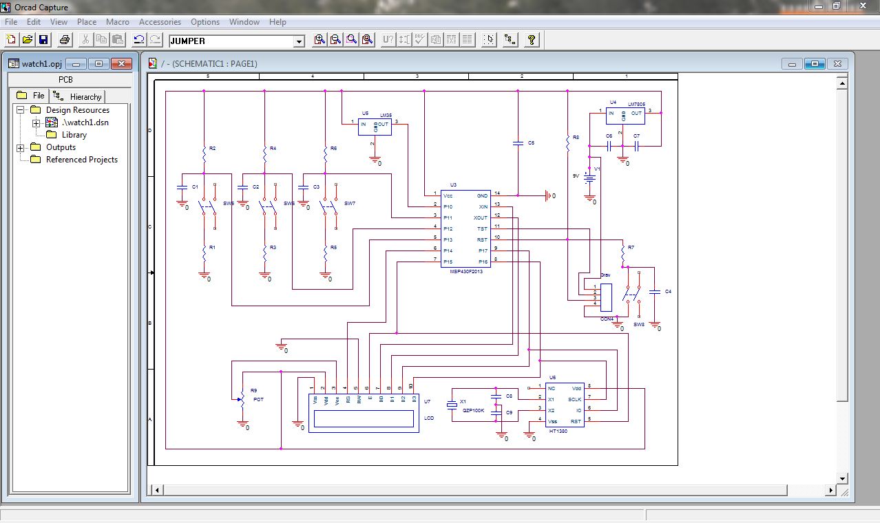
So with all libraries ready, we return to schematic and seek the libraries created at Place Part in the same place in which they were saved. After you have added all make the links as previously explained and presented in the template, getting the following schematic.


sexta-feira, 22 de julho de 2011

Criando um esquemático

 Agora estamos chegando mais perto da concretização do projeto físico, vamos então criar o esquemático do circuito do relógio, para depois fazer seu layout, confeccionar a placa, montar os componentes e testar.
Para criar o esquemático vamos utilizar o programa OrCAD® Capture da Cadence.
Abra, um novo projeto, e salve um como Schematic, para começar devemos incluir as bibliotecas em Place Part selecione os resistores (R/ Design Cache), capacitores (C/ Design Cache), chaves (sw KEY-SPST/ Design Cache), conector do gravador (CON4/ Design Cache), potenciômetro (POT/ Design Cache) e cristal (qzp100K / Design Cache).
A maioria dos componentes que precisamos há disponível nas bibliotecas, mas outros como LM35, LM7805, LCD, MSP e HT1380 não possuem biblioteca, por isso teremos que fazer as nossas.
Primeiramente crie uma nova biblioteca em Files, ressalte-a na janela de pastas e em Design crie uma New Part. Nomeie esta, como exemplo faremos a biblioteca do MSP então em Name é MSP430F2013, Prefix U e Footprint DIP14. Agora vá em Place e adicione uma Polyline de acordo com o formato do micro, em seguida adicione os 14 Pins em Place também preenchendo corretamente o nome e a numeração. Sua biblioteca está pronta, é só salvá-la e criar as outras.


Assim com todas as bibliotecas prontas, voltamos ao esquemático e procuramos as bibliotecas criadas em Place Part no mesmo lugar em qual foram salvas. Depois de adicionadas todas fazemos as ligações conforme anteriormente explicado e apresentado no modelo, obtendo o seguinte esquemático.


Com esta parte terminada, seguimos para o layout, mas isto é no próximo post, neste mesmo blog e neste mesmo dia da semana.
Até logo.

sexta-feira, 15 de julho de 2011

Power consumption


We come back today to talk about the current consumption of the clock, first noting that the following values may still not be definitive, because the project is still not completed, that is, there's still the possibility of changes in both components and on the way to link them. 
             
As the three buttons don’t consume too much when tight and basically nothing when not being used (just what the capacitor absorb), let's disregard the amount of current that they pull.
Then left over to do the calculations the following components: the LMs, LCD, R1, MSP, pot, and the HT1380.
Querying the datasheets (https://sites.google.com/site/embarcadosunifei/home/arquivos-do-blog), you can get details of current drawn by each components (except R1, which should be calculated).

The values are the following: 
Component
        µA
LM35
60
LM 7805
8000
R1
100
HT1380
1,2
Potenciômetro + LCD
45000
MSP430-F2013
220


    An important detail is in the pot, the LCD pulls itself 45mA for your backlight, and a value much lower for the rest, the pot function is precisely to prevent the LCD pull so much current.

Then when everything is ready the clock will have two modes, one in which the backligth this bound (potentiometer at minimum), and the other in which they can see what this written on the LCD (pot limit).
Then to the current calculations we will consider that the potentiometer and the LCD as a single component that can consume from 0 to 45 mA.
With this we have a consumption ranging from 8281.2 to 53281.2 µA.
For the calculation of the duration of battery let's round consumption as 8.3 – 53.3 µA.
A problem to determine the running time is the fact that the storage capacity of current batteries varies widely, rapidly searched and can find batteries ranging from 170-300 mAh.

Doing the calculations for a stack of 200 mAh battery would have an approximate length of 3.75-12:0 am.
I.e. could last from one day up to a few hours if you forget the LCD turned on. For sure a duration really small for a watch, I believe that nobody is willing to change the battery of the clock once per day.
            The measure to withdraw the LM7805 in would save 8 mA, what would you change the duration time for 151-666 h. what changes of 1 day for almost a month, ok still isn't much, but already greatly improves. But the best solution would even use the recorder's input to plug an external source adapted 5V which would not use the voltage regulator, reducing consumption.


So today that’s it, we are still discussing the best solution to our problem, and come back next week with another post.


sexta-feira, 8 de julho de 2011

Cálculo do consumo do relógio

           Voltamos hoje pra falar sobre o consumo de corrente do relógio, primeiro lembrando que os valores que se seguem podem ainda não ser definitivos, pois o projeto ainda não esta concluído, ou seja, ainda existe a possibilidade de mudanças tanto nos componentes quanto na maneira de ligá-los.
             
            Como os três botões consomem pouco quando apertados e basicamente nada quando não estão sendo usados (só o que o capacitor absorver), vamos desconsiderar a quantidade de corrente que eles puxam.
            Então sobraram para se fazer os cálculos os seguintes componentes: os LMs, LCD, R1, MSP,  potenciômetro, e o HT1380.
            Consultando os datasheets (https://sites.google.com/site/embarcadosunifei/home/arquivos-do-blog), pode-se obter os detalhes da corrente puxada por cada um componentes (exceto o R1, que deverá ser calculado).
            Os valores são os seguintes:


ComponenteValor da corrente em µA
LM3560
LM 78058000
R1100
HT13801,2
Potenciômetro + LCD45000
MSP430-F2013220


            Um detalhe importante está no potenciômetro, o LCD puxa por si próprio 45mA para seu backlight, e um valor muito mais baixo para o resto, a função do potenciômetro é justamente impedir que o LCD puxe tanta corrente.
            Então quando tudo estiver pronto o relógio terá dois modos, um em que o backligth esta ligado (potenciômetro no mínimo), e a outra em que não se conseguirá ver o que esta escrito no LCD (potenciômetro no máximo).
            Então para os cálculos de corrente iremos considerar que o potenciômetro e o LCD como um único componente que pode consumir de 0 a 45 mA.
            Com isso temos um consumo variando de 8281,2 a 53281,2 µA.
            Para o calculo do tempo de duração da bateria vamos arredondar o consumo como sendo de 8,3 – 53,3 µA.
            Um problema para determinar o tempo de duração é o fato de que a capacidade de armazenamento das pilhas atuais varia muito, uma rápida pesquisada e pode-se achar pilhas que vão de 170 – 300 mAh.

            Fazendo os cálculos para uma pilha de 200 mAh teríamos uma duração aproximada da bateria de 3.75 - 24 h.
            Ou seja poderia durar desde um dia inteiro até algumas horas se você esquecer o LCD ligado. Com certeza uma duração realmente pequena para um relógio, acredito que ninguém esteja disposto a trocar a bateria do relógio uma vez por dia.
            A medida de se retirar o LM7805 nos pouparia 8 mA, o que mudaria o tempo de duração para 151 - 666 h. O que muda de 1 dia para quase um mês, ok ainda não é muito, mas já melhora bastante. Mas a melhor solução seria mesmo usar a entrada do gravador para plugar uma fonte externa adaptada de 5V que  não usaria o regulador de tensão, diminuindo o consumo.
      
Então por hoje é isso, ainda estamos discutindo a melhor solução para nosso problema, e voltamos semana que vem com mais um post.

Até mais.

sexta-feira, 1 de julho de 2011

Choosing the components


Today our discussion is about the connections between the microcontroller and peripherals.
As important as certain components, or their links, are also the values used, follow  two examples:
A capacitor used to debounce won't work for a very low value, and will affect the speed of the button if it is too high.
Already a poorly chosen can give a resistor voltage drop very low and fry the next component, a drop too high could cause the component bound hadn't enough voltage to "connect".
The HT1380 is responsible for external clock, and must be used along with a Crystal, its clock 500kHz, then we will use is a crystal of 33kHz.
The LM is a 7805 voltage regulator, will be used to download the 9V voltage to 5V stack that will be used in the circuit. To use it you should take special care not to invert the pins.
The LM 35 is a temperature meter that can measure temperatures from -65C to 150C, I do not think anyone go take our watch to the South Pole nor inside the oven, then this component will be enough for our needs. This component also requires correct placement of the pins.
The following is a table with the values of the components your codes adopted in schematic and their functions. 


Componente
Valor
Função
U1
MSP430F2013
Microcontrolador
HT
1380
Clock externo
LM 7805
5V
Regulador de tensão
LM 35
5V
Sensor de temperatura
R1
47KΩ
Resistor
R (2-10)
10KΩ
Resistor
C (1-5)
100nF
Capacitor
C (6,7)
5pF
Capacitor
Pot1
10KΩ
Potenciômetro
Osc
32KHz
Cristal 
Bat
9V
Bateria (Vcc)
J1
-
Conector
S (1-4)
-
Botão  

You can find the datasheet of the components in our site https://sites.google.com/site/embarcadosunifei/home/arquivos-do-blog:

Below there’s a picture to clarify the correct positioning of the LMs:


The following image is Schematic of our future clock:
The sign "*" in capacitors and resistors mean that they are not absolutely required, the resistors are pull-ups, and the capacitors are for debounce.